
습관만들기 (재도전)
PEMFC and PEMEC 비교 본문
아래 논문을 참고했습니다.
Wang, Yun, et al. "PEM Fuel cell and electrolysis cell technologies and hydrogen infrastructure development: a review." Energy & Environmental Science (2022). https://doi.org/10.1039/D2EE00790H
PEM Fuel cell and electrolysis cell technologies and hydrogen infrastructure development – a review
Polymer electrolyte membrane (PEM) fuel cells or PEMFCs and PEM electrolysis cells or PEMECs are two closely related electrochemical devices having a similar structure: a PEM with catalyst layers (CLs) coated on its surfaces, flow fields, and bipolar plate
pubs.rsc.org
아래 포스팅을 참고했습니다.
https://m.blog.naver.com/agentenergy17/221407718811
연료전지: PEMFC - MEA (Membrane Electrode Assembly)
안녕하세요~ PEMFC 포스팅으로 가열차게 달리는 중인 agent. carrot 입니다 ♨♨ 앞 포스팅에서 ME...
blog.naver.com
PEMFC와 PEMEC 핵심 부품인 PEM (보통 -40~120℃), CL, BP (일반적으로 60~80℃, CO2 X, 65~80% 효율)
ALEC, AMEC, SOEC 많은 electrolysis cell 중 왜 PEMEC냐?
AMEC, SOEC vs ALEC, PEMEC (durability & performance 상대적으로 뛰어나 상용화된 전기분해 셀)
ALEC (low operating current density & high maintenance cost) vs PEMEC
그럼 PEMFC와 PEMEC는 어떤 차이점이 있는가?
1. electrode reactions, 2. catalyst materials, 3. operating pressure range
특히 PEMEC의 cathode에서 HER은 low Pt loading에서도 일어나는 쉬운 반응, 반면 anode에서 sluggish OER은 귀금속으로 Ir 또는 IrOx를 이용해서 overpotential을 줄여야 함
| PEMFCs | PEMECs | |
| Operating temperature | -40 ~ 120도 (보통 80도) | 25 ~120도 (보통 60 ~ 90도) |
| Operating pressure | 1 ~ 2 atm | 1 ~ 50 atm |
| Durability target/performance | light duty FECV: 8000h heavy duty FECV: 30000h stationary fuel cell: 80,000~130,000h |
20 years or over 90,000 h by 2030 |
| Cost target | light duty FCEV: 30 dollar/kW heavy duty FCEV: 60 dollar/kW |
2dollar/kg hydrogen 1dollar/kg hydrogen within a decade |
PEMFC 구조: End plate + 집전판 + BP (flow field + GFC) + Electrode-anode (substrate->MPL->CL) + Electrolyte (membrane) + Electrode-cathode (CL->MPL->substrate) + BP (GFC + flow field) + 집전판 + End plate
GDL: substrate + MPL - 반응 기체를 CL로 전달 및 물 거
PEM: 양성자 전달, 산소 및 수소 분리
CL: HOR, ORR 촉진
PEMEC 구조: End plate + 집전판 + BP (flow field + GFC) + Electrode-cathode (substrate->PTL->CL) + Electrolyte (membrane) + Electrode-anode (CL->PTL->substrate) + BP (GFC + flow field) + 집전판 + End plate
| Baseline Materials | ||
| PEMFC | PEMEC | |
| Component | 10~14 | 15~20 |
| Membrane | 10-50 $\mu m$ thick PEM; Nafion | 100-200 $\mu m$ thick; Nafion |
| CL | 0.1-10 $\mu m$ thick; Porous layer (pt-based catalyst nanoparticles), catalyst support, ionomer Catalyst: 1-5 nm Carbon particle: 10-100 nm CL's pore size: 100 nm Pt loading: 0.1-0.4 $mg/cm^2$ |
1-10 $\mu m$ thick; Porous layer with catalyst nanoparticles (Ir-based: anode, Pt-based: cathode), with/without catalyst support (semi-conductive metal oxide e,g. TiO2 and Nb2O3 Ir-based catalyst particle: 1-10 nm Ir loading: 0.2-2.0 $mg/cm^2$ |
| GDL/PTL | Carbon fiber-based paper with PTFE MPL is coated on the CL side of a GDL GDL pore size: 20-50 $\mu m$ MPL pore size: 0.1-1.0 $\mu m$ GDL thickness: 100-200 $\mu m$ MPL thickness: 50 $\mu m$ |
Anode (PTL): sintered porous Ti sinter or perforated Ti sheet (50-500 $\mu m$ thick) Pore size: 20-100 $\mu m$ Ti surface is plated with Pt or Au for corrosion protection Cathode (GDL): carbon fiber based porous layers |
| BP | Metallic plate, graphite plate, composite plate: provide pathways for heat and electron transfer and mechanical support for electrodes |
Metallic plate, composite plate: must resist corrosion, provide pathways for heat and electron transfer and mechanical support for electrodes |
| Flow field | Flow channel configuration or porous media flow fields for gas reactant distribution and water removal. Parallel, serpentine, pin type flow are common channel depth: 0.3-1.0 mm |
Flow channel configuration for liquid water supply and oxygen gas removal Parallel flow fields are common channel depth: 1.0 mm |
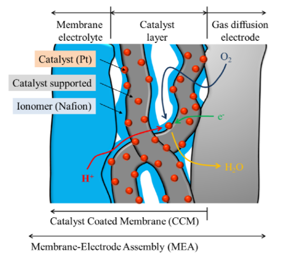
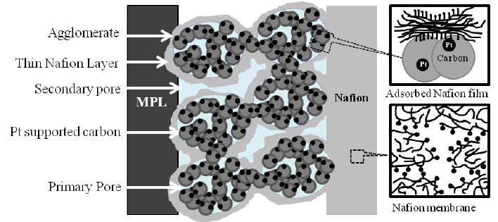
CL: 여러가지 단계로 구성됨 (1) carbon support with electrocatalyst nanoparticles dispersed on the surface, (2) ionomer binder, (3) porous network -> 특히 PEMFC의 ORR, HOR 은 Pt으로 설계됨 -> electrochemical reaction 발생
GDL: (1) electric connection btw BP and CL, (2) pathways for reactant transport and heat/water removal, (3) mechanical support for MEA, (4) protection of the CL from erosion by gas flows
PTL: PEMFC의 GDL과 유사하지만 two-phase flow를 촉진시킴. PEMEC anode는 Ti를 주로 사용함 (high conductivity, corrosion resistance, mechanical robustness). Anode PTL을 보호하기 위해 metallic coating 필수 (Pt, Au, TiN). PEMEC의 cathode PTL/GDL로 carbon-fiber porous layer를 사용하여 단가를 낮춤
BP: (1) mechanical support for PEMFCs, (2) conductive pathways for heat and electron conduction / materials: non-porous graphite (장점: corrosion resistance, high electrical conductivity; 단점: high gas permeability, brittle structure -> durability 문제), carbon composites (polymer binder e.g. epoxy resin and polypropylene & carbon fillers e.g. graphite powder and carbon black -> polymer binder: mechanical strength, gas impermeability 제공; carbon fillers: pathways for electron and heat conduction 제공 -> 둘의 최적 비율 찾기), Metallic BPs (Al, stainless steel, Ti의 장점: high electric and thermal conductivities, low gas permeability, mechanical robustness; 단점: corrosion in acidic environment -> protective film 필수)
PEM material: PFSA (PTFE backbone structure) 주로 사용되며 그 중 Nafion 사용
Membrane: 이온은 통과하되, 전자는 통과하면 안됨
Sulfonic acid group (highly hydrophilic) as an end group of the side chain (H+ 부착되어 RSO3H 형태의 작은 기공들 형성)-> adsorption of water (H2O와 결합하여 SO3-와 H3O+로 변형) -> provide the main pathway for proton transport (H3O+가 H2O와 만나 H+ 가 계속 이동하는 Grotthus mechanism), SO3-에는 다시 H+가 결합 -> water in the Nafion membrane은 proton transport 가장 중요한 요인 (그래서 PEMFC는 가습이 필수적임) -> side chain의 $SO^-_3$가 $H_2O$와 만나서 $SO^-_3H_3O^+$ 이온 사이트를 형성 -> percolation mechanism 양자가 움직일 수 있는 공간을 형성하여 proton transport 구현

membrane hydration (막 수화): ionic conductivity 위해서 필수적임 / Side chain 길이: chemical stability & performance 중요한 요인
PEM structure: cluster model 적용 -> Stokes-Einstein equation via the migration mechanism -> current density calculation / Two mechanism ("hopping (Grotthus)" and "vehicular") -> proton transport 설명
Grotthus mechanism: 결합했다 끊어졌다를 반복하며 양성자가 이동하는 것

GDL이 마이크로 다공성 층 (MPL) 및 소수성 처리 (PTFE)로 구성 -> MPL이 CL과 맞닿은 방향, PTFE가 BP와 맞닿은 방향 -> PTFE는 소수성으로 막 내부의 물이 빠져나가는 것을 방지 (물이 빠져나간다면 막이 건조하게 되고 높은 저항=낮은 성능
이오노머 (ionomer): 공중합체 (이온성이 없는 반복 단위와 이온을 함유하는 반복단위로 구성) = 공유결합과 이온결합을 동시에 소유하는 열가소성 플라스틱으로 이온결합의 정전기력이 고유의 물성을 띔. 교차이온결합 (Ionically crosslinked) 구조로 극성 이온기가 가역성을 띔, 그러니 열을 가하면 이온 결합이 인력을 잃고 고분자 사슬들이 자유로워짐 → 수소 이온 전도가 가능한 고분자 (보통 Nafion SO3-), 촉매와 혼합하여 촉매 층에 얇게 도포되어 촉매 층이 서로 분리되지 않도록 유지하는 접착제와 같음, 즉 반투막으로 이온 선택성을 가짐 (엄청난 물을 흡수)
HT-PEMFC를 위해서는 PA-PBI spray를 membrane 막 (CCM, catalytic coated membrane) or GDL 내 substrate (CCS, catalytic coated substrate)에 함
바인더 (binder): 촉매를 바인딩하는 역할로 GDL이나 CL에 첨가함
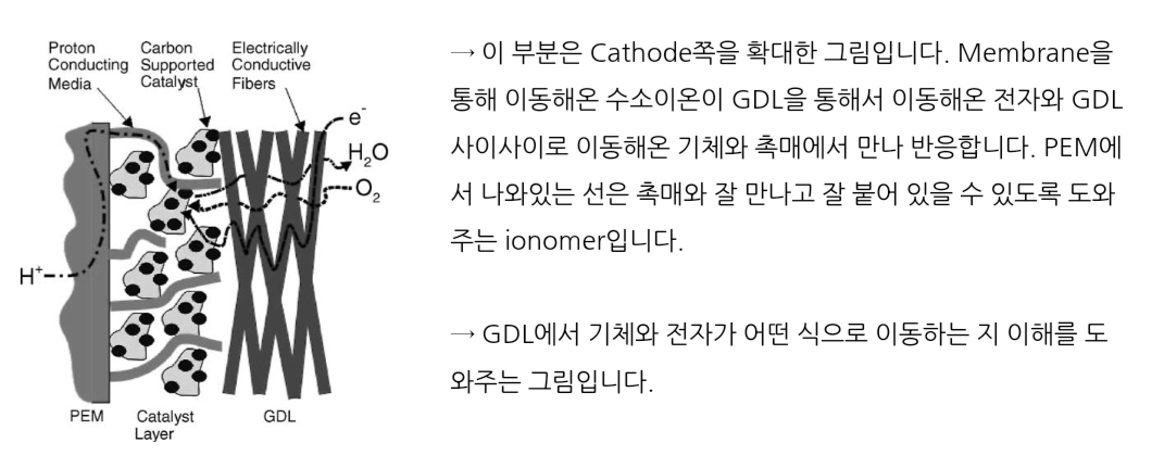
H+ (PEM과 CL이 연결된 ionomer network를 타고 들어옴), 전자는 GDL의 carbon fiber를 타고 anode에서 전극을 타고 넘어 들어옴, 산소는 cathode에서 공급되어 GDL의 MPL 기공으로 들옴 -> CL의 carbon 위 Pt에서 반응이 일어나서 물이 발생함 -> 물이 CL의 ionomer network와 기공을 통해서 GDL의 MPL 기공으로 동 (substrate 소수성으로 BP로 못가게 함) -> 막의 가습상태 유지
Water in PEM: three mechanisms (concentration-gradient driven diffusion, electro-osmotic drag, hydraulic permeation)
PEMFC: water back-diffusion & EOD 중요 (EOD는 $SO^-_3H_3O^+$ 로 anode -> cathode 물 이동, anode 쪽 dryness 유도, 반면 water back-diffusion 은 EOD로 cathode 쪽에 물의 농도가 높아져 다시 anode로 돌아와 anode의 수화에 중요한 요인) / PEMEC: EOD & hydraulic permeation 중요
3가지 메커니즘을 계산하기 위해서 아래의 변수가 계산돼야 함
Water content (water uptake) [# of $H_2O/SO_3H^-$ groups]: $\lambda=f(a)$, a: water activity (Nafion 117)
Density: $\rho=f(\lambda)$
Ionic conductivity [S/m]: $\sigma_m=f(\lambda)$
Water diffusivity [m2/s]: $D^m_w=f(\lambda, T, \alpha_a)$, $\alpha_a$: transfer coefficient of anode -> Tafel equation으로 계산
Electro-osmotic drag coefficient: $n_d=f(\lambda, T, \alpha_a)$
Hydraulic permeability [cm2]: $K_m$은 Nafion에 따라 결정됨
Gas diffusivity [m2/s]: $D^m_{O_2}, D^m_{N_2}, D^m_{H_2}$는 Nafion에 따라 결정됨
전해질막과 활성층 모두 ionomer 상으로 양자전도도는 가습 상태에서 최대 (양자가 ionomer의 소화 영역으로 이동) -> 전기장력에 의해 H3O+가 cathode 쪽으로 이동 -> H3O+ 형태로 이동된 물이 환원극에 쌓이면 농도차로 물의 back diffusion (anode로 이동) 발생 -> 건조한 ionomer 상태에서 술폰산 결합의 해리 불가능 -> 전도도가 감소 (300배 차이) -> 낮은 이온 전도도로 양자가 촉매 표면에 접근하는 것을 방해 -> 심각한 건조 조건은 전해질 막의 열화 유발
물을 과도하게 공급할 경우 -> 물이 GDL의 기공을 들어가 가스의 이동을 방해 (flooding) -> 가스의 확산을 막음 -> 가스 유로 출구와 가까운 곳에서 낮은 전류 밀도가 출력 -> 불균형 유발 -> 전극의 젖음성과 기공이 물로 채워져 국부적인 출력 전류 밀도가 0에 가까움 -> 전지 전압이 아주 천천히 하강-> 물방울이 뭉치면서 가스 유로를 막아 촉매 쪽으로의 가스의 확산을 방해 ->급격한 전압 강하 발생 -> flooding은 가스 유로보다 물이 생성되는 활성층과 가스확산층에서 더 먼저 발생함.
결국, Proton and water transport 매우 중요함
Proton transport: ohmic voltage loss and Joules heating 관련 -> Joules heating increase local temperature -> hot spots will increase ionic resistance or current density
Water transport: thickness -> 두꺼우면 water back-diffusion 일어나기 힘들어서 EOD만 발생하여 anode의 dryness가 심화되어 수화가 힘듬 / 특히 PEMEC는 anode와 cathode의 큰 압력 차 유지가 요구됨 -> membrane thickness 큼 -> ohmic voltage loss 지배적 (reactant flow로 물을 사용하므로 anode의 dryness는 고려 X)
또한, Waste heat이 발생함 -> multiple mechanisms (irreversible heating, entropy heating, Joule heating, removed by the BP surfaces or cooling channels)
| Component | Physical and electrochemical processes | |
| PEMFC | PEMEC | |
| Membrane | Water transport (diffusion, EOD, hydraulic permeation) Gas ($H_2, O_2, N_2$) cross-over Heat production (Joule heating) Heat transport (conduction) |
Water transport (hydraulic permeation and EOD) Hydrogen cross-over Heat production (Joule heating) Heat transport (conduction) |
| CL | HOR in anode, ORR in cathode $H^+$ transport in ionomer network $e^-$ transport in carbon network Water transport in the pore and ionomer networks Oxygen diffusion in the pore network and across the ionomer thin film Heat production (reversible entropy heat, irreversible heat due to overpotential, Joule heat, and latent heat during phase change) Heat transport (mainly conduction) |
HER in cathode, OER in anode $H^+$ transport Liquid water flow in pore network $e^-$ transport in the catalyst network $O_2$ gas flow in the pore network Heat production (reversible heat due to entropy change, irreversible heat due to overpotential, Joule heat, and latent heat during phase change) Heat transport (mainly conduction) |
| GDL or PTL | Cathode: Oxygen and water vapor transport (diffusion) Anode: Hydrogen and water vapor transport (diffusion) Liquid water transport Heat transport (conduction) including heat pipe effect Electron conduction |
Cathode: Oxygen-water vapor gas transport Liquid water flow Heat transport (conduction) Electron conduction |
| BP | Heat transport (conduction); electron conduction | |
| Flow field | Liquid water droplet dynamics on the GDL; two-phase flow in channels (usually mist or film flow) and at heterogeneity (expansion to manifold) | Gas bubble dynamics on the anode PTL; two-phase flow in channels (usually bubble flow) |
3.5 Multiphysics processes and fundamentals
PEMFC (polymer electrolyte membrane fuel cell)와 PEMEC (polymer electrolyte membrane electrolysis cell) 모두 아래의 1-3번은 동일하게 적용
- PEMFC의 cathode에서 물이 생성되어 산소의 공급을 방해하는 flooding 현상에 의한 transport loss 중요
- PEMEC는 물의 투입하므로 flooding 현상을 고려할 필요가 적음
1. Performance loss mechanisms
(1) Activation loss
- PEMEC의 anode에서 OER (oxygen evolution reaction) 또는 PEMFC의 cathode에서 ORR (oxygen reduction reaction)에서 sluggish kinetics로 주로 발생함
- PEMEC의 cathode에서 HER (hydrogen evolution reaction) 또는 PEMFC의 anode에서 HOR (hydrogen oxidation reaction)에서 무시가능 (CO와 같은 불순물이 없을 경우)
- exchange current density는 PGM (platinum group materials, Pt)를 사용하여 높임
- specific surface area는 nanoparticles와 rough CL (catalyst layer) 구조를 사용하여 100-1000배 높임
(2) Ohmic loss
- protonic and electric currents에 의해서 발생함
- PEM의 ionic resistance는 CLs, GDLs (gas diffusion layer), BPs (bipolar plate)의 electric resistance와 비교했을 때 훨씬 높음
- 상업용 PEMEC는 두꺼운 Nafion 115와 117을 사용하여 anode에서 cathode로 수소가 crossover하는 것을 방지 -> high current density에서 ohmic loss가 매우 커짐
- PEMFC는 proton과 water의 transport 저항을 줄이기 위해서 두께가 얇음 (10-20$\mu m$), 그래서 ohmic loss는 주로 무시하나 PEM 또는 anode의 CL이 건조하면 고려
(3) Mass transport loss
- PEMFC는 상대적으로 높은 전류밀도 ($>1A\cdot cm^{-2}$)에서 cathode의 산소 공급을 방해하여 cell performance를 낮춤, oxygen diffusivity와 liquid fraction이 매우 중요한 요인임
- PEMEC는 transport loss는 무시할 정도면 엄청 높은 전류밀도 ($>5A\cdot cm^{-2}$)에서 산소가 빠르게 발생하여 물이 촉매에 접근하는 것을 방해하여 성능이 떨어짐
2. Electrochemical kinetics
Butler-Volmer equation: $j=ai_0 \lgroup e^{\frac{\alpha_a}{RT} \cdot F \cdot \eta}-e^{\frac{\alpha_c}{RT} \cdot F \cdot \eta} \rgroup$, a: specific area (surface-to-volume ratio of active catalyst 측정)
Surface overpotential: $\eta=\Phi^{(s)}-\Phi^{(m)}-U_0, \quad U_0=1.229-0.9(T-298.15)+\frac{RT}{zF} ln(\frac{a_{H_2} a^{0.5}_{O_2}}{a_{H_2O}})$
Sluggish ORR or OER -> Tafel equation & Rapid kinetics HER or HOR -> linear approximation B-V equation
Phase potential $\Phi^{(s)}, \Phi^{(m)}$: driving forces for electron and proton transport
Law of conservation of charge: $0=\nabla \cdot (\sigma^{eff}_{s} \nabla \Phi^{(s)})-j, 0=\nabla \cdot (\sigma^{eff}_{m} \nabla \Phi^{(m)})+j$
$\sigma^{eff}_{s}, \sigma^{eff}_{m}$: conductivity for electrons and protons
- PEMFC에서 liquid water or ice는 catalyst surface 위에 발생하여 specific area a를 감소시킴 $a=a_0(1-s)^{\tau_s}$
- PEMEC에서 oxygen bubble은 catalyst surface 위로 발생하여 anode의 OER 반응을 방해함 $a=a_0s^{tau_s}$
- PEMFC는 relative humidity가 local PEM hydration에 영향을 주어 inonic resistance가 국지적으로 차이가 나고 전체적으로 current distrubtion의 차이가 심함
3. Multiphase (Two-phase) flow
- ORR's water production in PEMFC or OER's oxygen production in PEMFC에서 주로 발생함
- PEMFC의 liquid water는 oxygen supply를 방행하고 transport loss를 증가시키는 주요 원인
Challenges and Opportunities
1) CL: PGM-based electrocatalysts에서 PGM을 줄이고 동일한 성능과 지속성을 유지하도록 소재 개발
catalytic activity = mass activity (nano-structuring, supporting, reshaping) + intrinsic activity (alloying, core-shell structure, element confinement) / 후자는 overpotential 감소하여 electrical efficiency 올려줌
비싼 Pt를 줄이고 상대적으로 싼 Co, Ni, Mo를 합금하여 성능을 올렸으나 durability가 떨어짐 -> HSC (high surface carbon)과 LSC (low surface carbon)을 적절하게 섞어서 carbon corrosion과 Pt dissolution/aggregation 줄임 -> Mn-N-C와 Fe-N-C 비귀금속으로 성능 0.6 W/cm2 달성, 그러나 poor durability -> 4가지 원인 de-metallization, metal oxidation, carbon corrosion, dissolution of active metal sites
2) PEM
PEMFC에서 1. humidification 필수 (flooding 문제), 2. 두꺼운 Nafion 115와 117 (큰 ionic resistance=ohmic loss)
고온 PEM 제안됨, 특히 SOEC (solid oxide electrolysis cell)은 600℃ 이상에서 작동함 -> 그러나, material degradation과 수 많은 어려움으로 상용화 힘듬 -> Intermediate-temperature electrolysis (120-300℃) portfolio 등장함
HT-PEM (120-180℃)은 flooding 해결 가능 (Nafion은 고온에서 분해되므로 다른 물질을 찾아야함)-> 고온 작동 시 CO에 대한 음극 촉매의 높은 내성으로 CO 제거장치 불필요 (장점1), 전극 반응역학이 강화되어 Pt의 충전량이 낮아도 됨 (장점2), 비가습 조건에서 물관리가 쉽고 외부가습을 위한 공간과 에너지 최소화 (장점3) -> 그러나, 충분한 양자 전도도를 위해 높은 가습이 요구되나 무수 양자전도체는 전하 캐리어로 물을 요구하지 않음 (양자 전도도 $10^{-3}~10^{-2} S/cm 매우 작음)
대체물질: PSF (polysulfones), PEEK (polyetheretherketones), PBI (polybenzimidazoles) -> acid-doped PBI PEMs (PA PBI) 가장 유망함: free of humidification -> acid leaching으로 long-term durability에 문제 -> 최근 poly (2,3,5,6-tetrafluorostyrene-4-phosphonic acid) membrane 200℃에서 효과적인 이온전도도를 유지함, 240℃에서 1740mW/cm2
PBI: close chain packing (rigid structure, strong hydrogen bonding) -> low gas permeability -> doped with acid for conductivity -> But, low mechanical strength -> 상반되는 trade-off를 최적화하기 위해 ionic cross-linking, covalent cross-linking, composite membrane을 사용 (Sulfonated partially fluorinated arylene main chain polymer 추천)
고온 환경에서 우수한 내열성과 기계적 특성 (고강도, 내마모성), 물 이외의 이온 불순물 최소화, 최저의 열팽창 계수 및 최고의 압축 강도, 리간제에 의한 주사슬 공격으로 자유로워 상대적으로 산과 염기에 강함
'전기화학' 카테고리의 다른 글
| Indirect/Direct Ammonia Fuel Cell (0) | 2023.03.20 |
|---|---|
| In-situ formed Metal Pyrophosphates (MP2O7)/PA/PBI (0) | 2023.03.10 |
| The Fuel Cell Route (Power-to-X) (0) | 2023.03.09 |


